  %20&%20NOx%20%20reduction%20Diesel%20Chehroudi.jpg)
-
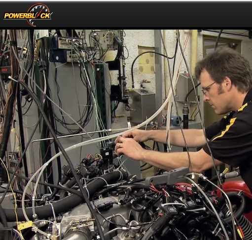
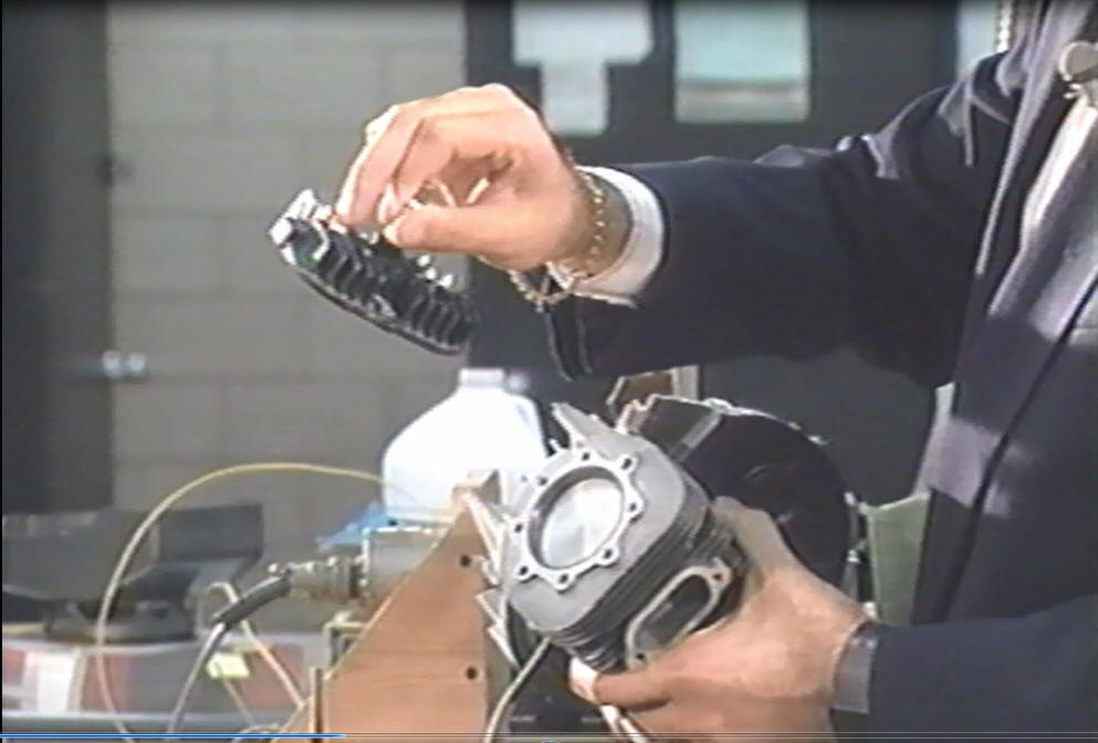
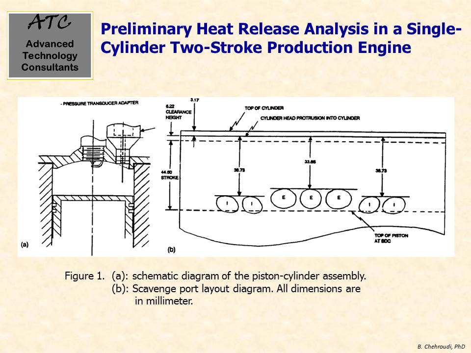
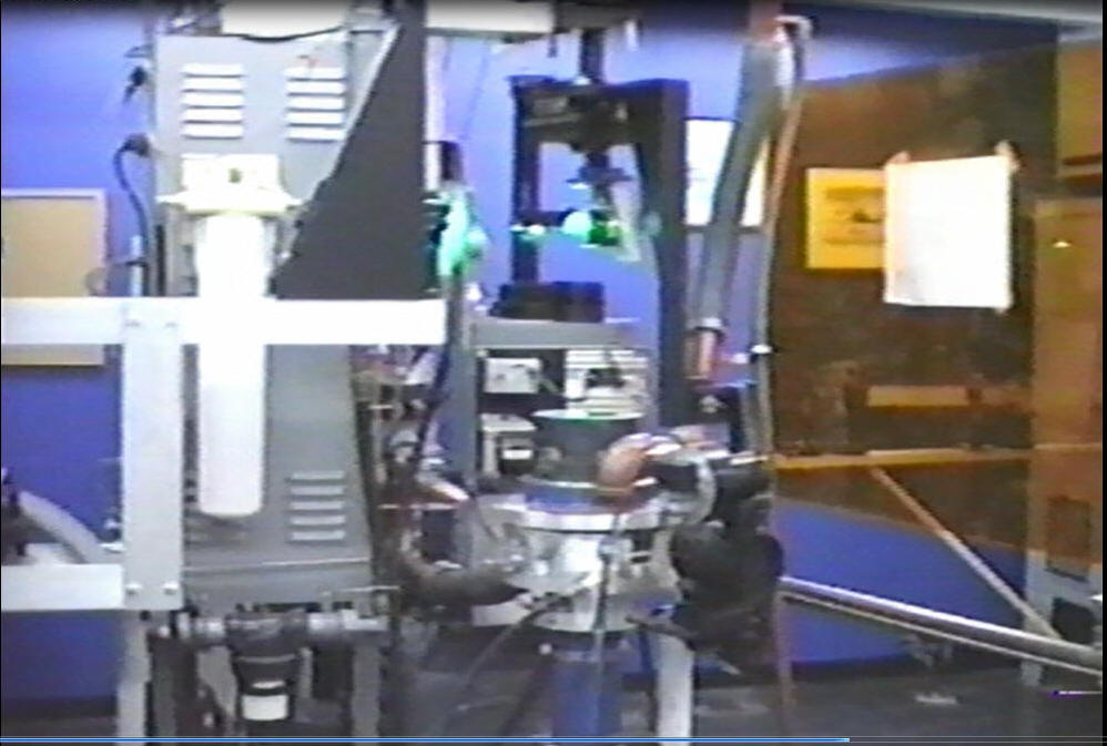
This video
clip (click on the right image to run the video) shows a test setup of a single-cylinder small two
-stroke gasoline-fueled engine on a small dynamometer. The
engine head is equipped with a pressure transducer to provide
traces for combustion signature diagnostics. In this case, a
one-zone model is used to calculate the heat release rate and
mass fraction burned information to understand the combustion
characteristics of this engine.
-
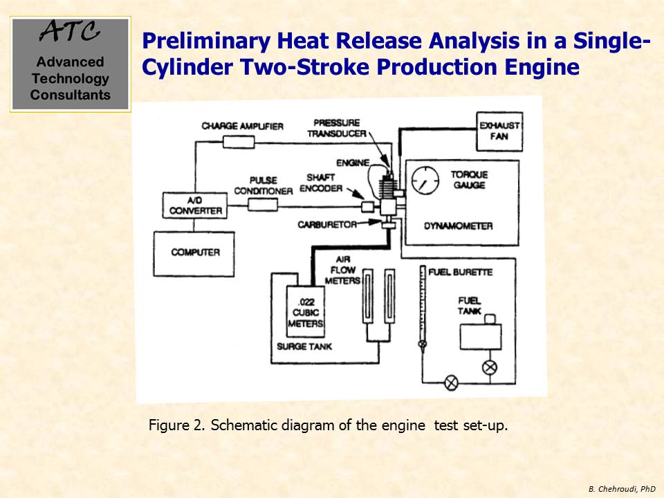
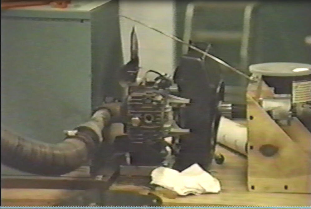
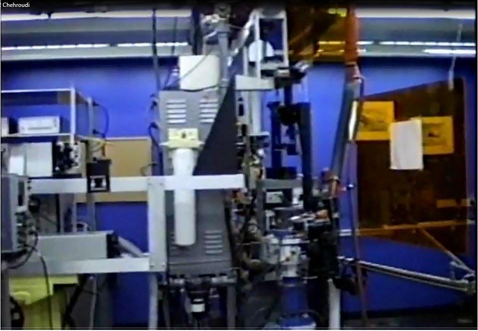
This video clip
(click on the right image to run the video) describes a small engine
test setup showing a dynamometer along with necessary piping
system for the
intake and exhaust as well as measurement systems needed for air
and fuel flows rates into the engine/
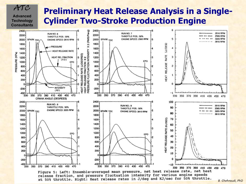
Results have been published in the literature. For
example, see Rohrer, R. and Chehroudi B., 1993.
Preliminary Heat
Release Analysis in a Single-Cylinder Two-Stroke Production
Engine, Society of Automotive Engineers, 1993 Congress and
Exposition, SAE Transaction Paper 930431, March 1-5.
-
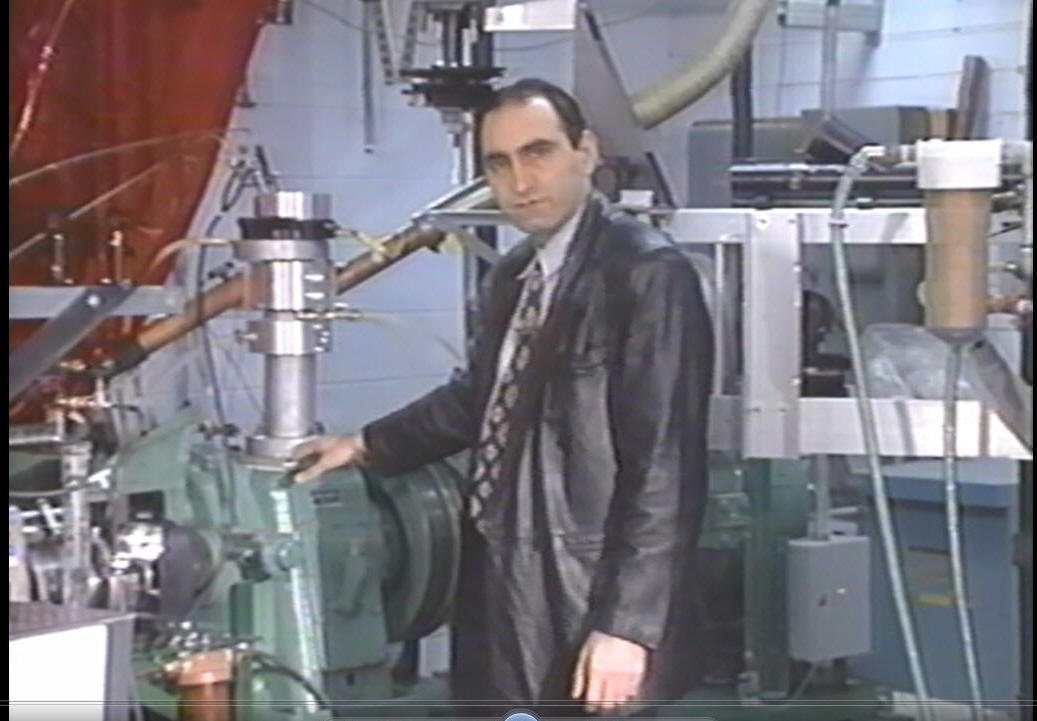
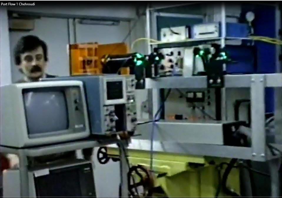
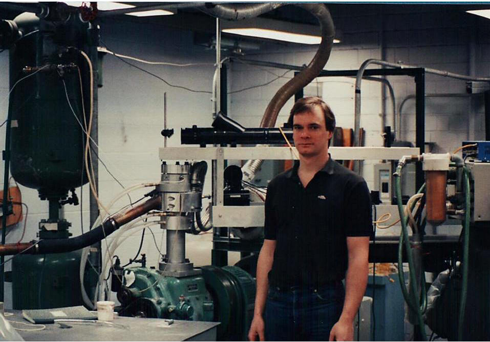
This video
clip (click on the right image to run the video) shows operation of
an engine for intake port flow measurements using Laser Doppler Velocimeter (LDV). The entire transmitting optics are on a
lathe machine base to enable precise XYZ traverse for
easy optical alignment/measurement purposes as well as achieving
convenient rotation of portion
of the transmitting optics along the engine axis for rapid
intake port flow measurements (engine was under two-stroke operation).
The person in the image is
Konstantinos Boulouchos who was a visiting researcher to
the
laboratory (currently a professor at the ETH Zurich,
Switzerland).
Results have been published in the literature. For
example, see Bardsley, M. E. A., Boulouchos, K., Gajdeczko, B.,
Chehroudi, B., and Bracco, F. V., 1989.
Measurements of the
Three Components of the Velocity in the Intake Ports of an I. C.
Engine, Society of Automotive Engineers, 1989 Congress and
Exposition, SAE Transaction Paper 890742, February 27 - March 3.
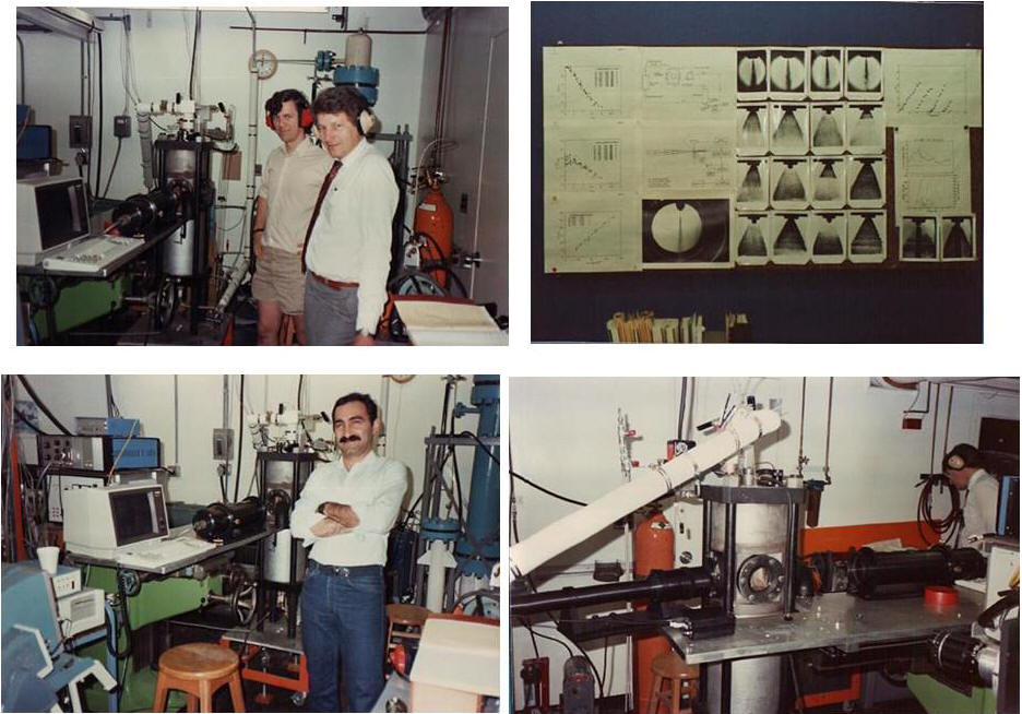
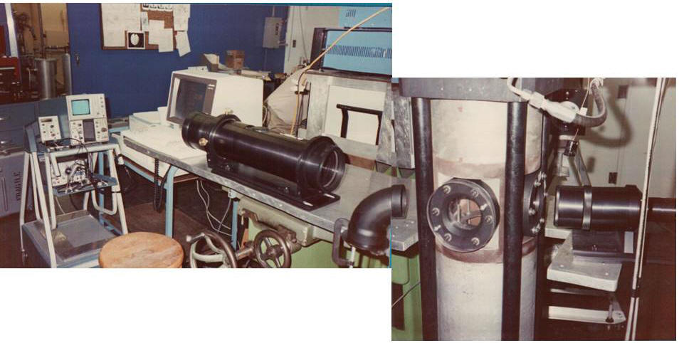
-
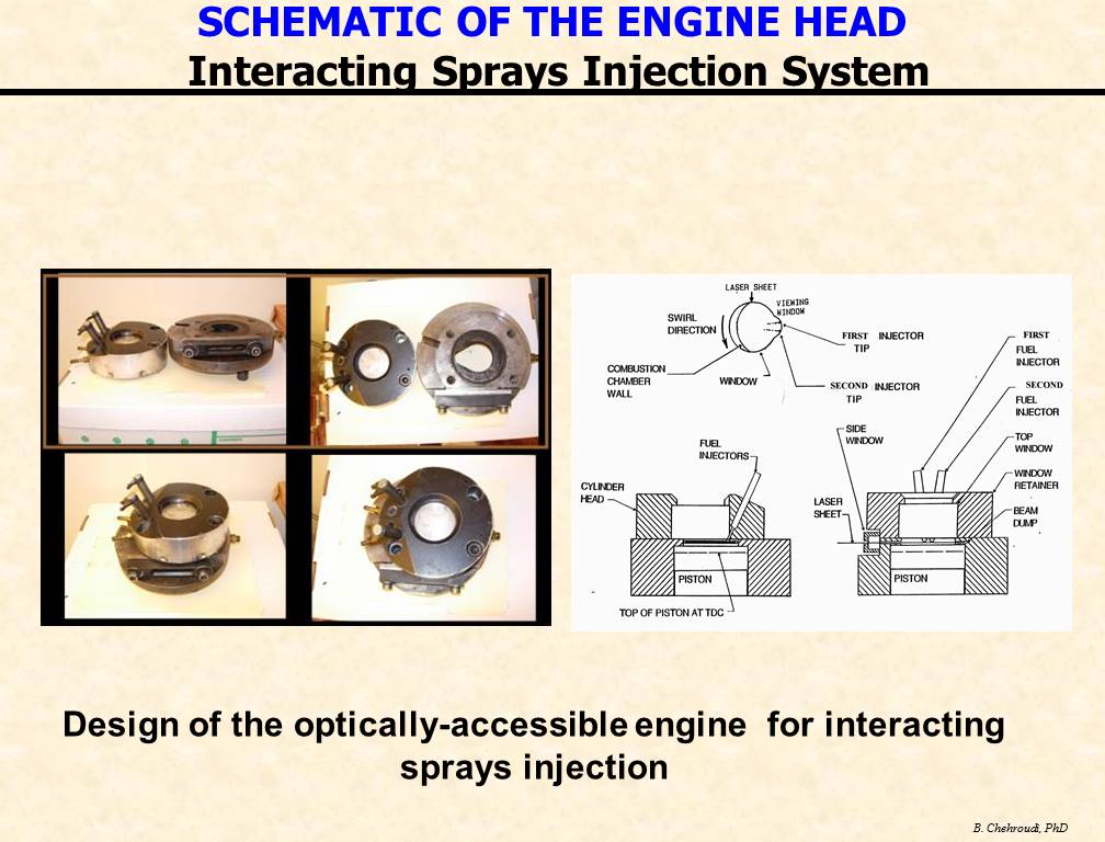
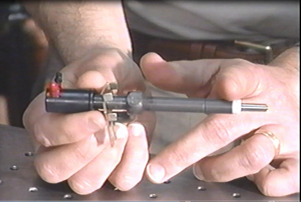
The images to
the right show an optically accessible engine for
combustion and flow studies using laser diagnostics such as
Laser Doppler Velocimeter (LDV), Phase Doppler Particle Analyzer
(PDPA, Exciplex method, high-speed visualization of in-cylinder
phenomena, and spectroscopy. The engine head can be readily
changed for either compression ignition (diesel) or spark
ignition (SI) engine studies.
Results have been published in the literature. For
example, see Schuh, D. and Chehroudi, B., 1992.
LDV Measurements
of Intake Port Flow in Two-Stroke Engine with and without
Combustion, Society of Automotive Engineers, 1992 Congress and
Exposition, SAE Transaction Paper 920424, February 24-28.
-
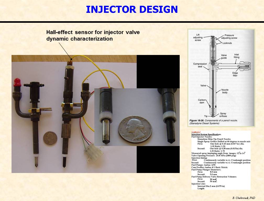
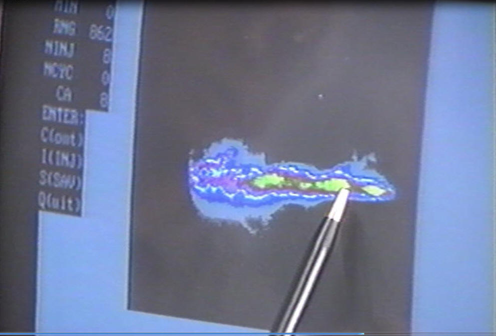
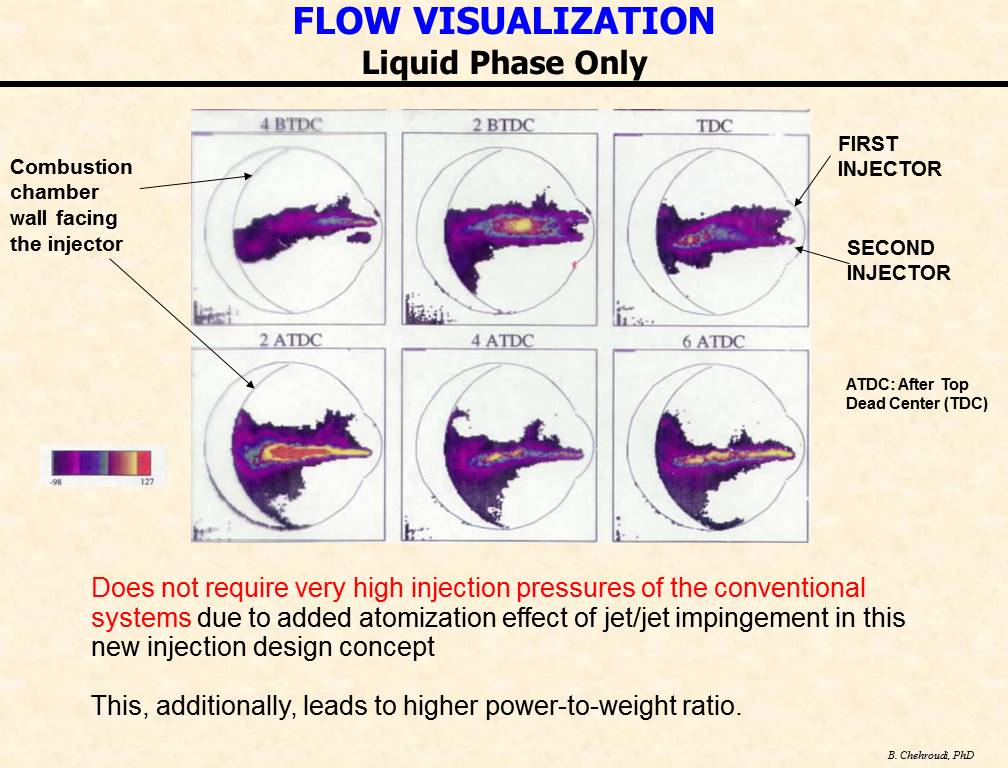
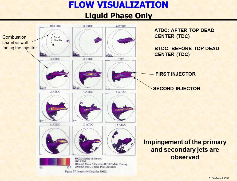
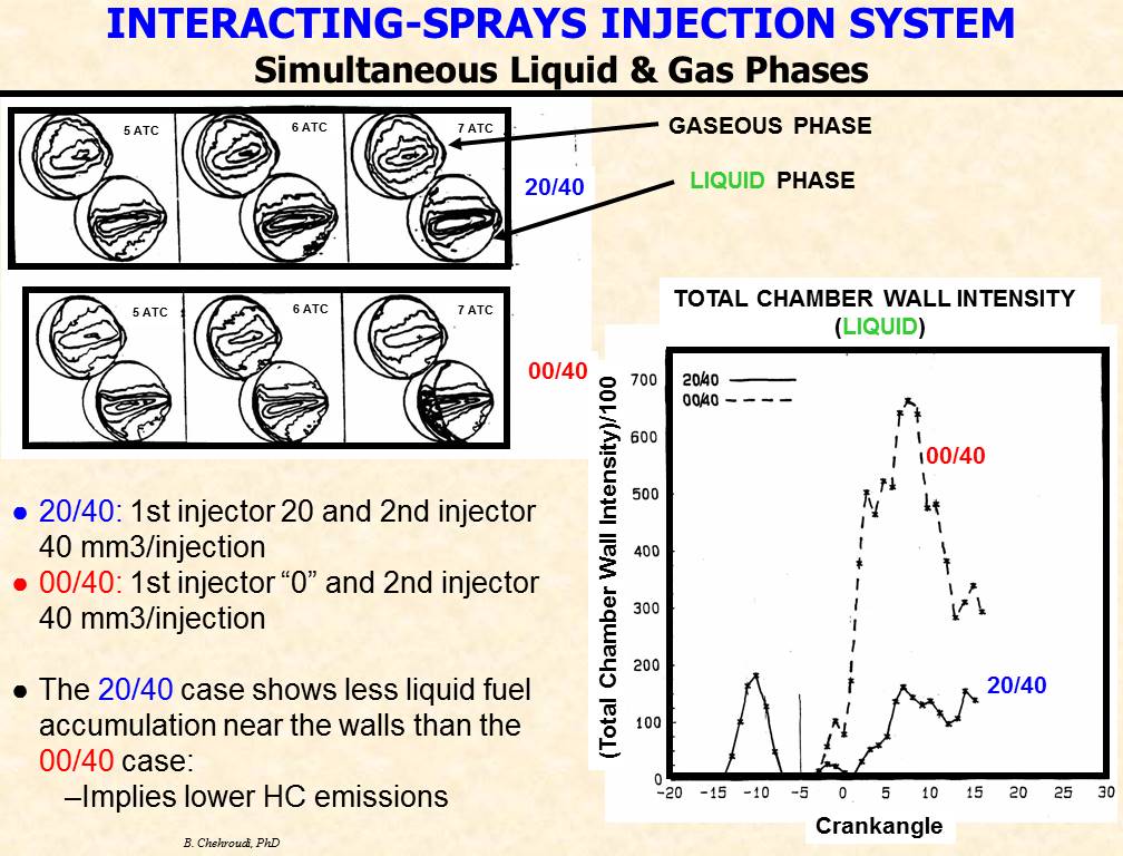
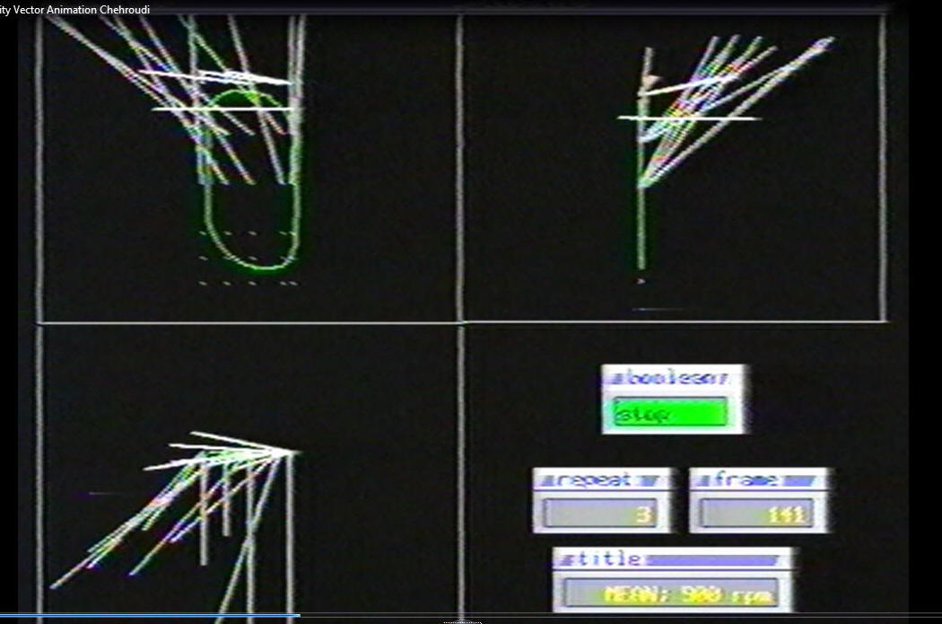
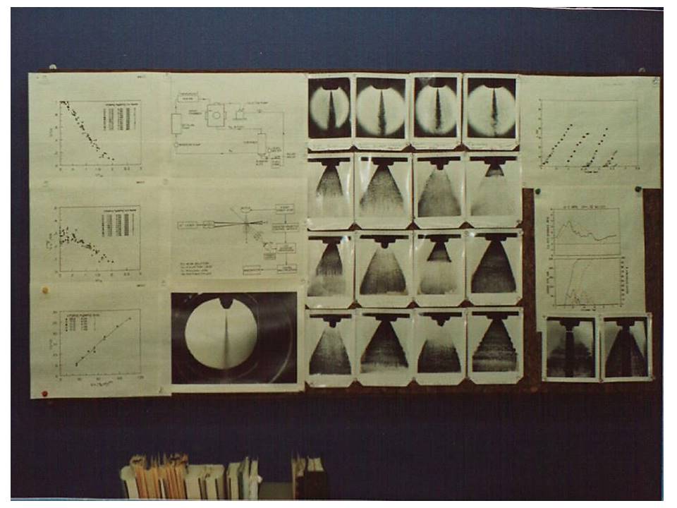
Sample images
acquired from a diesel-type spray (upper row) and
conically-opening poppet injector designed for Direct Injection
Stratified Combustion (DISC engine program) combustion studies
are shown.
The DISC program was a collaboration by General Motors Research
Laboratory, Princeton University Engine Research Laboratory, Los
Alamos National Laboratory, and Sandia Combustion Research
Facility sponsored the US Department of Energy (DOE).
-
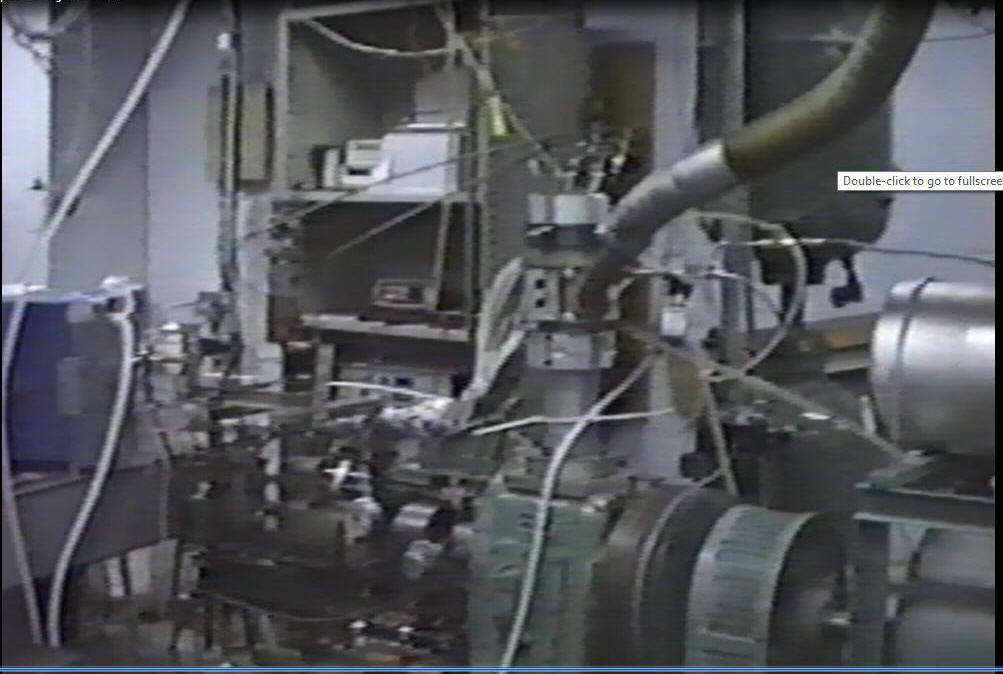
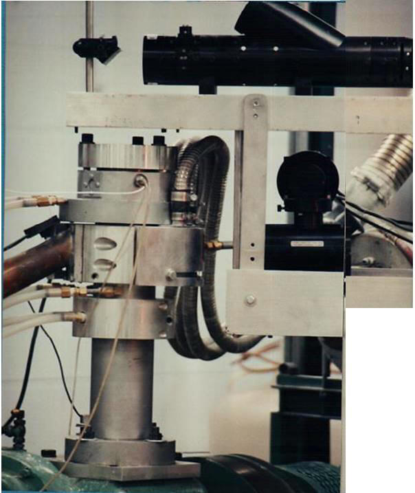
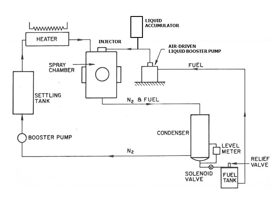
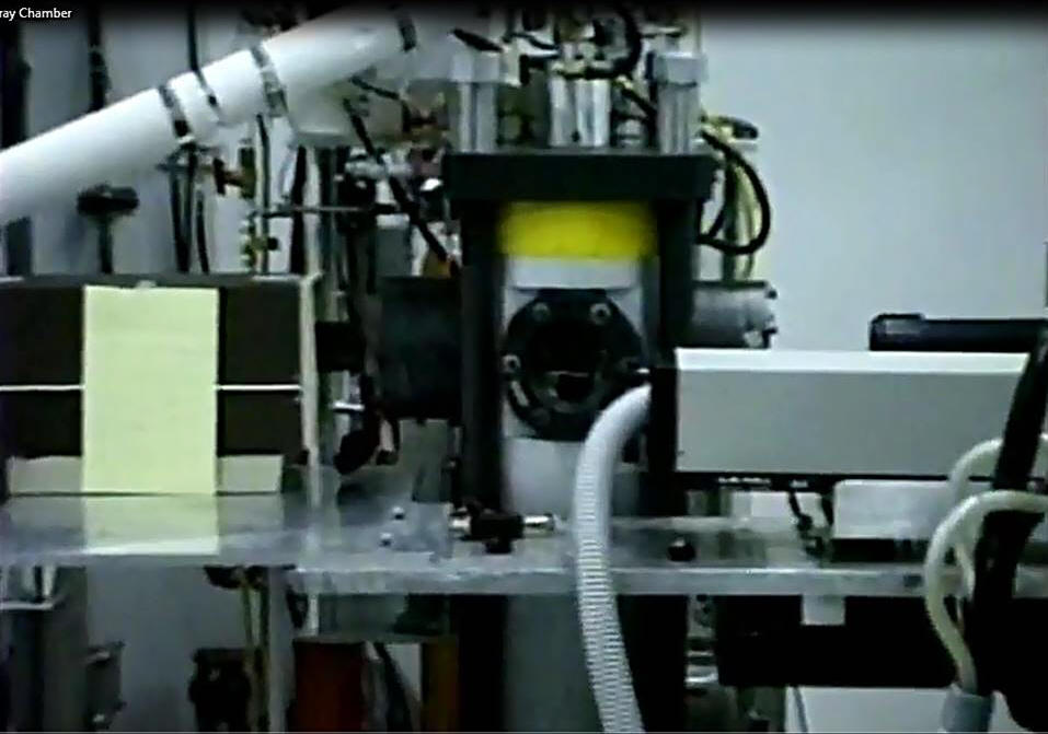
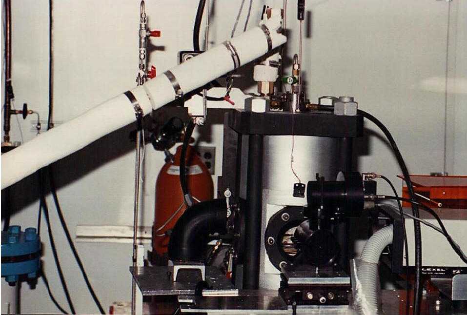
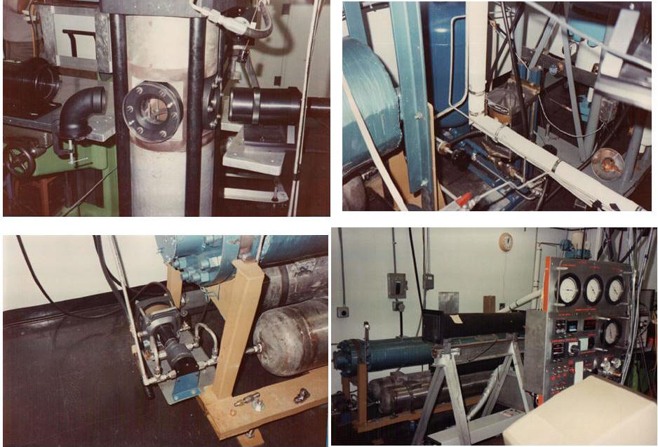
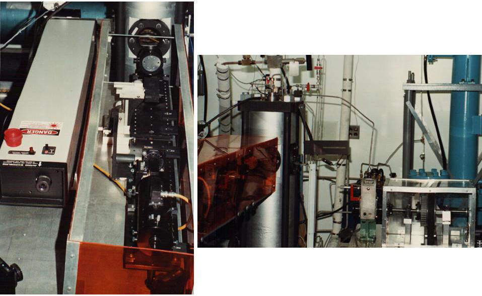
Images of the
high-pressure and temperature spray chamber for liquid
atomization and fuel injection research and development
are shown.
The pictures show a setup for laser optical diagnostics to
map spray droplet size and velocity fields. In
the movie clip, a setup for transient spray
characterization of a gasoline direct injection system by Ford
DFI-3 using a diffraction-based drop size distribution (by
Malvern) can be seen.
Results are published in the literature.
For example, see Laforgia, D, Chehroudi B. and Bracco, F. V.,
1989. Structure of Sprays from Fuel Injections - Part II, The
Ford DFI-3 Fuel Injector, Society of Automotive Engineers, 1988
Congress and Exposition, SAE Transaction Paper 890313, February
27- March 3.
Back to Top of
This Page
NOTE:
Contact Advanced Technology Consultants for consulting needs
and opportunities in this area.
Copyright 2017 -
Advanced Technology Consultants- All Rights
Reserved
|